High measurement speeds, extraordinary precision and optimal resolution all at once …
these are not mutually exclusive!!
Electrical testing will always be torn between achieving the highest precision and at the same time accomplishing the shortest test duration possible. While electrical safety tests with their fixed minimum test times hardly offer any potential for optimization, the possibilities for improving measuring speeds in functional and quality tests are in turn quite different:
Measurement speed
Time schedules of functional and quality tests result from the product properties and our own quality requirements – but not exclusively! Especially the technological approach in test equipment design is of vital significance here.
In most cases, testing devices are incorporated in time-optimized chains of production. The devices need to be both fast and reliable and cannot become a “bottleneck” in the process.
Your requirement: “The test device must provide maximum performance in all its operation modes”.
This concerns the entire software and especially the efficiency of each individual test method. All safety tests and most of the functional and quality tests are essentially based on electrical measurements, which are already evaluated during or, at the latest, at the end of each test step.
The decisive factor for the total measurement time is the fastest measurement speed possible. However, this must not impair measurement precision!
Extraordinary precision: from analog signals to digitally measured values – technological features for geeks
The basis of all calculations in the test device are digitally measured values.
So how do you get from an analog signal to a digital measured value?
Analogue to digital converters are used to do so..
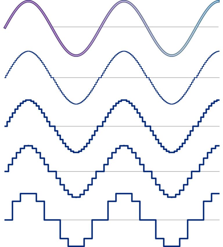
The analog signal course is converted into digital single values with these semiconductor chips. A digital single value is also called a sample. For example, if you measure 1000 single values per second, you speak of a sampling rate of 1 kSps.
The graph shows that the precision of a measurement depends on the number of samples in a period of time and on the “staircase” shaped resolution of the analog signal.
To the point:
The smaller the time interval between the individual samples and the finer the resolution of the amplitude, the more accurately the digital measurement values represent the analog reality.
This leads to precise and reproducible measurement results.
Optimum resolution – maximum measurement accuracy
High measurement accuracy is only achieved at the expense of measurement speed, and vice versa. This is a basic engineering principle. It has been like this in the past and will continue to be so in the future.
This becomes particularly clear when using a very accurate tabletop/ built-in multimeter in a test device. Some test device manufacturers tend to use such multimeters. The accuracy is certainly good, but the measuring speed is often very modest. And that again is contrary to the requirement that an automatic test instrument should not be a bottle neck in terms of measurement speed.
Another disadvantage of multimeters is that they do not provide individual sampled values but only completely processed effective or DC voltage values. As a result, a lot of very important detailed information for special signal analyses and fast reactions to highly dynamic test events is lost.
How does SCHLEICH tackle this problem?
SCHLEICH engineers have always developed the measurement hardware as well as the software on their own.
As a result, all measurements are perfectly tailored to the required precision of each individual test procedure.
Optimized measuring speeds in combination with high measuring accuracy form a perfect unit.
It is our mission to offer the fastest testing equipment – without any compromises in measurement accuracy.– Dipl. Ing. Martin Lahrmann
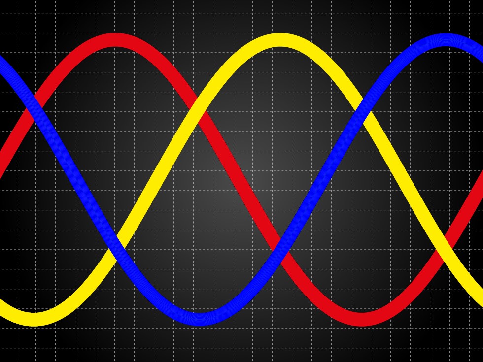
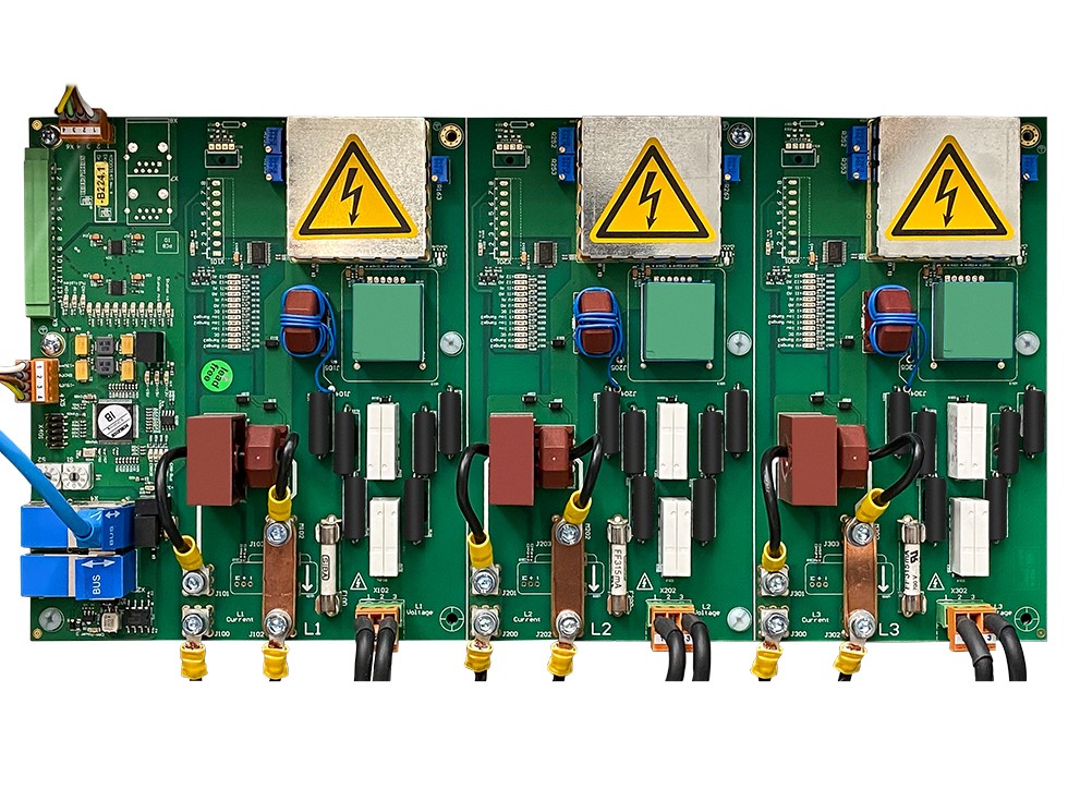
New three-phase current measurement technology
Functional tests are performed in the range from lowest to highest currents. Currents from 0.1 mA to over 1 kA are not uncommon. This is an enormous dynamic range. Slow measurement technology with time-consuming autorange switching is unsuitable. This is another significant disadvantage of multimeters.
The measurement must therefore be carried out with a high sampling rate and high resolution. It must determine the effective values of the half or full periods and the DC voltage component with grid period accuracy.
SCHLEICH measuring technology has always been powerful. But even tried and tested products can be improved with new technological opportunities.
Therefore, we have carried out a comprehensive upgrade of our three-phase measurement technology. The result is even more precision and even more speed. Needless to say, a full in-house development.
For our core philosophy is: We have to keep all the threads in our hands at all times and must not be dependent on externally sourced components and their disadvantages.
Key parameters of three-phase measurement technology
| voltage measurement | from 0,1 V to 600 V ULN – measured against a virtual neutral point |
| from 0,1 V to 1000 V ULL | |
| potential-free measurement | |
| resolution up to 24 bits | |
| accuracy class rating better than 0,1 | |
| current range | from < 0,1 mA to > 1000 A |
| potential-free measurement | |
| current converter on board | |
| external current converters > 1000 A, e.g. LEM / DANFYSIK | |
| external shunts | |
| resolution up to 24 bits | |
| accuracy class rating better than 0,1 | |
| sampling rate | up to 2000 kSps |
| Ethernet | 1 GBit |
| Measurement | 2-channel single phase measurement, instantaneous – 1xU plus 1xI, fully time-synchronized |
| 6-channel three-phase measurement, instantaneous – 3xU plus 3xI, fully time-synchronized | |
| 12-channel measurement, instantaneous – 3xU plus 3xI plus 6 free channels, fully time-synchronized | |
| power measurement | actual values, instantaneous |
| apparent power, active power, reactive power, instantaneous | |
| power factor cos φ | included |